Saturday, July 4, 2015

Old Rail Lantern RGB LED Retrofit


I was browsing the local Habitat For Humanity Restore (they recycle and resell building materials) for another project and stumbled across these awesome lanterns. They are old kerosene lamps - which meant plenty of room in the base for electronics. I immediately thought of the WS2812B LED arrays I had coming and picked them up before anyone else could grab them. ($10 a piece! A quick look online shows them selling for $80-$150 per from collectors!).

After some fiddling, I decided to use the 24 LED circle array, and found that it sit nearly perfectly inside the glass globe. I threw together a quick prototype using a MakeyMakey (Atmega32u4) I had lying around and stuffed the LED ring in to the glass with some white paper for diffusion. I used the Adafruit Neopixel Strand test demo library just to see how it would look - and I was very happy with the results.


I decided I wanted to have a simple switch for power, and push button to cycle between modes. I also wanted it to be battery powered. I didn't want to use an entire Arduino for this project, so I grabbed an ATtiny85 - which looked like it would suite my needs perfectly - 5v/8Mhz is plenty to drive the LEDs, and at those speeds it doesn't require an external clock or any other hardware.

For the program, I settled on using the FastLED library over the Adafruit Neopixel library because it let me set up several color palettes using very little memory, and with only 8Kb of memory for a program I was going to need every byte.

The code was a challenge for me - this was the first time I've worked with addressable RGB LEDs, and this was the first time I'd had to write code that was constrained to 8Kb. My initial attempt on the MakeyMakey clocked in at around 12Kb - and after much trimming and optimizing (though admittedly I imagine it could get smaller) I manged to get it down to 8,126 bytes - just under the 8.192 bytes I had available using 6 different 16 bit color palettes, along with software debounce and variable delays in the color changes.

You can see my final code on Github - RGB Lantern

After getting the program down to size and loaded on the ATtiny85 - I prototyped the circuit on a breadboard and ensured that everything worked.
Fritzing Sketch of the breadboard layout

Once I was satisfied there - it was time to solder it on to the protoboard. I started by securing the LED ring the the board, then attaching the 5v regulator.


 Then I tested the circuit before adding the power switch.

I was hesitant to drill in to the lantern at all - but looking closely I noticed there was a notch cut in the frame just below the glass that was the perfect size for the switch to sit. I soldered some lamp cord to the switch, applied some heat shrink tubing, and fit it in.


I Soldered the switch wires to the circuit, and squeezed the wires from the button through the holes you see at the bottom of the lamp. Wiring it all up, the circuit was ready to go!

And complete!

 A video of the modes in action is below.


Tuesday, February 24, 2015

Arduino Wireless Temperature Master

Part 2 - The Master 
Part 1 - The Nodes

In this post - I'm going to look at the wireless node master that will handle the input from the 3 wireless nodes I have around the house (from the previous post) using NRF24L01+ 2.4ghz transceivers.

The wiring of the Arduino for this part is relatively simple as I'm going to use a full size Arduino Uno.

Wiring


The NRF24L01+ wired to the Aruino Uno

Uno NRF24L01+
13 SCLK
12 MOSI
11 MISO
7 CSN
6 CE
2 IRQ
3.3v Vcc
GND GND

The wiring here differs slightly in the pin numbering from the previous project because I'm leaving room on Pin 8 for a 433Mhz receiver (for another stage of the project). I'm also using Pin 2 connected to the IRQ pin of the transceiver - this will allow us to use an interrupt to process the data as soon as the transceiver receives it, without having to poll the unit constantly.

Interacting with the RF24 Module

My node master code is on Github.

I use the RF24 Library for my Arduino code. Download the Library and include it in your code.

The first thing I wanted to do was figure out what information I wanted to transmit. Basically, I wanted to get the temperature the node was reporting, the internal voltage, the battery voltage, the uptime of node, and the address of the node. To do this, I build a struct data type on both the nodes and the master - this makes it easy to transmit a complete package of information: Structs.h
#ifndef structs_h
#define structs_h

typedef struct {
  volatile unsigned long _micros;
  volatile float temp;
  volatile long Vcc;
  volatile int Vbatt;
  volatile byte address;
  volatile long uptime;
} dataPacket;
#endif

The volatile keyword in the data structure means that when the Arduino accesses that variable, it always uses the value in RAM. This allows the value to be updated during an interrupt, and be reflected no matter where or when the value is read.

Now, in the main program, I import all the relevant packages
#include "SPI.h"
#include "nRF24L01.h"
#include "RF24.h"
#include "printf.h"
#include "structs.h"

I store the addresses for the nodes in an array, and create the node variables I will store the info in:

byte address[][6] = {"0node","1node","2node","3node"};
// master radio in address[0]
byte master = 0;
int myAddress;

dataPacket dataPackage;
dataPacket node1;
dataPacket node2;
dataPacket node3;
dataPacket empty;

Next - initialize the radio
const int rPin1 = 6; // radio pins, SPI plus 7,6
const int rPin2 = 7; 
RF24 radio(rPin1,rPin2);

In setup():
1. Begin the radio interface
2. Disable auto acknowledge - this means that the sending and receiving radios won't acknowledge packets. It will increase packet loss but save battery life
3. Open up read ports for each address - this will allow each node to write to this unit
4. Open up a writing port for the master address - this isn't being used currently but would allow us to talk back to each node
5. Power the radio on
6. Enable the listening interface
7. Print the radio details for debugging 8. Enable the pin mode interrupt on Pin 0 (digital pin 2 on the Uno) - when this pin is pulled low, the radio has received a packet and it will call the check_radio function

void setup(){
  #if defined DEBUG
    Serial.begin(38400);
  #endif
  Serial.println("Start");
  printf_begin();
  radio.begin();
  radio.setAutoAck(false);
  
  // open pipes for communication
  for (int i=1; i < sizeof(address) - 1; i++) {
    radio.openReadingPipe(i, address[i]);
  }
  radio.openWritingPipe(address[master]);
  // power up radio
  // this takes up to 5ms
  radio.powerUp();
  delay(10);
  radio.startListening();
  
  radio.printDetails();
  
  //interrupt on pin 2 (interrupt 0)
  // Will be pulled LOW when receiving
  attachInterrupt(0, check_radio, LOW);
  
}

The check_radio function is called whenever an interrupt is received on Digital pin 2 - which means the radio has done something.

  1. It checks to see what happened - packet sent, or received? This will be received in our case.
  2. It reads the data in to the dataPackage variable - this contains all the information we want from the node.
  3. It parses the dataPackage, and depending on the address puts it in one of 3 node variables.

void check_radio(void)       
{
  #ifdef DEBUG
    Serial.println("IRQ received");
  #endif
  
  bool tx,fail,rx;
  radio.whatHappened(tx,fail,rx);    // What happened?
  
  if ( tx ) {                        // Have we successfully transmitted?
      // Do nothing
  }
  
  if ( fail ) {                      // Have we failed to transmit?
      printf("Failure\n");
  }
  
  if ( rx || radio.available()){     // Did we receive a message?
    radio.read(&dataPackage, sizeof(dataPackage));
    unsigned long time = millis() / 1000;
    if (dataPackage.address == 1) {
      node1 = dataPackage;
    } else if (dataPackage.address == 2) {
      node2 = dataPackage;
    } else if (dataPackage.address == 3) {
      node3 = dataPackage;
    }
  }
}

Currently, as this is just a proof of concept/debug setup - the loop() function simply prints the latest information it has every minute.
void printInfo(dataPacket data) {
  Serial.print("Up: ");Serial.print(data.uptime);Serial.print("s, ");
    Serial.print(data._micros);Serial.print(", ");
    Serial.print(data.temp);Serial.print(", ");
    Serial.print(dataPackage.Vbatt);Serial.print(", ");
    Serial.print(data.Vcc);Serial.print(", ");
    Serial.println(data.address);
    return;
}

void loop() {
  startTime = millis()/1000;
  int elapsed = startTime - endTime;
  if (elapsed == interval) {
    Serial.print("heartbeat (s): ");
    Serial.println(startTime);
    endTime = startTime;
    
    // every interval, display current information
    if (node1.address) {
      Serial.print("Node 1 -  ");
      //Serial.println(time);
      printInfo(node1);
    }
    if (node2.address) {
      Serial.print("Node 2 -  ");
      //Serial.println(time);
      printInfo(node2);
    }
  }
}

This gives us this output every minute:
Current information 52140
Node 1 - Up: 3320s, 34056211, 13.00, 7.82, 5.00, 1
Node 2 - Up: 3231s, 24546830, 21.50, 10.04, 5.02, 2

The next step is going to be to clean up the interface, and add in a 433Mhz receiver to receive from a LaCrosse TX9U wireless weather station.

Programming an Arduino Mini with an Arduino Uno

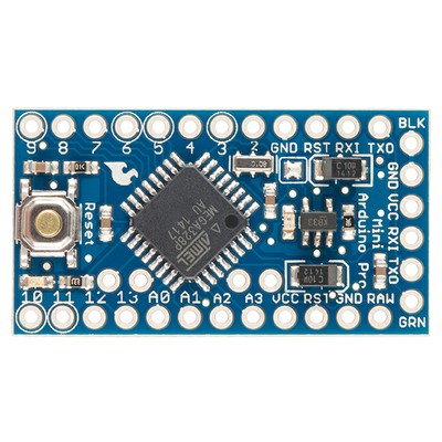
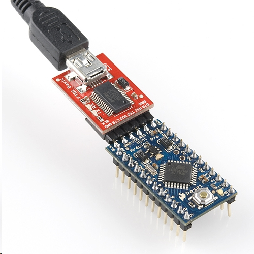
The Arduino Pro Mini is a fantastic bit of kit - but it lacks an on-board USB driver which means programming it has to be done through a serial interface.

Most guides use an FTDI cable/board.
Which is probably the easiest way to do it - however if you don't have one handy you can also use another Arduino you might have laying around. In my case, I had an Arduino Uno.

Wiring

Wiring the Mini to the Uno


Uno Pro Mini
RX RX1
TX TX0
GND GND
5v Vcc

This tripped me up a bit originally - the Uno RX goes to the Mini RX1 pin, and the Uno TX goes to the Mini TX0 pin. It's opposite what you might expect - except that when using the Uno as a programming interface you are bypassing the ATMega328 on the Uno and essentially the Mini becomes the ATMega that the USB interface uses. Which means you want the RX/TX pins to line up the same.

From here - you have two options for programming the Mini. In both cases - I had to manually press the reset button on the Mini as soon as the upload started so the bootloader was in the proper state to accept new programming. You can wire the Uno RESET to the Mini's BLK pin and the IDE is supposed to be able to reset the Mini on demand - but I wasn't able to get it working.

Option 1

Remove the ATMega328 chip from the Uno board. When you upload the sketch, it will go directly to the Mini with no problems.

Option 2

If you don't want to remove the ATMega chip from your board, or you have an SMD Arduino Uno where you can't remove the chip, you can bypass it. To do so:
1. Unplug the Uno from USB
2. Hold the reset button down on the Uno
3. Plug in the USB cable to the Uno, keeping the reset button down
4. Press upload in the Arduino IDE
5. Once upload is complete, release the reset switch.

I like option 2 because there is less risk of damaging the Uno's ATMega328 pins when removing and reinstalling the chip.

Monday, February 23, 2015

Arduino Wireless Temperature Nodes

I've started working on a wireless network of temperature nodes - using a cheap 2.4Ghz transceiver, an arduino mini, and a cheap DS18B20 digital one-wire temperature sensor. The wireless nodes will run on batteries, so I want to reduce power consumption as much as possible.

Currently, I'm running 3 wireless nodes, communicating back to a main Arduino. In the near future I'll be building a logging interface so that I can track everything.

I selected the Arduino Mini because I wanted something small enough to go directly on to a breadboard, and the Mini was cheap from Deal Extreme - cheaper in . Total cost breakdown per node is:
1x Arduino Mini - $4.39
1x Small 400 tie breadboard - $3.21
1x DS18B20 Temperature Sensor - $1.99
1x NRF24L01+ 2.4Ghz transceiver - $2.22 (not pictured)
2x 1MOhm, 1x 4.7kOhm resistor - $0.02
1x 2AA Battery Holder - $1.61
3x 1N4001 Diode - $0.45 (not pictured)

Total: $13.89

I really like the Arduino Mini for its size. The 5v version I got is pretty much identical to the larger Arduino Unos - with the exception that they don't have a USB interface. You'll need an FTDI USB Cable, or another Arduino to program it. (I used an arduino uno - pictured - to program it. You can either remove the ATMega from the Arduino Uno, or just hold the reset button down while plugging the USB cable in and for the entire time you upload the sketch)
The Mini in front of an Arduino Uno

Now - for the wiring of the nodes. This is a Fritzing sketch that outlines how the Mini is wired, before adding the NRF24L01+ module:
Bare schematic with just the mini, and the temperature sensor

The top power rail is GND/5v, the bottom power rail is Battery v/GND. I'm using 2x 3.7v Trustfire Li-Ion batteries with 900mAh power. This is because 2x standard 1.5v batteries wouldn't give me enough voltage to run the 5v arduino. One of the nodes is running with a 4 battery pack though - and it's working just fine.

From the left side - there are 2 1M Ohm resistors, going from the Battery to ground - this acts as a voltage divider - reducing the voltage by half and going in to Analog 0. This is so that I can measure the battery voltage, which will be over the 5v that the Arduino can handle. The max voltage of my li-ion batteries is 4.25v, so with 2 of them and the voltage divider - the highest voltage the Arduino will see on this input is 4.25v.

I use 1M Ohm resistors because the higher the resistor value, the lower the constant drain on the batteries is. 1M ohm is the highest I had on hand - so that will give me a current draw of about 3 µA (0.003 mA) for this circuit.

Next to the left is the DS18B20 temperature sensor. It is wired to the Arduino's digital pin 4 - with a 4.7k Ohm resitor on the data pin to ground. This is a great little sensor - capable of making measurements in 0.5C increments in as little as 90ms.

The two orange wires from D9 and D5 are optional address select pins. This allows me to use the same code on all the nodes, and just connect different pins to ground to choose a different address.

This is what it looks like in the real world - minus the battery pack:

The Mini all wired up, minus the 3 diodes, the 2.4Ghz transceiver, and the battery case
As it stands here - this will let us measure the temperature. However, we still need to add a transmitter.
NRF24L01+

I chose the NRF24L01 partially because it was cheap, but also because it's very low power. When the radio is powered down it consumes about 1 µA - and only 9mA when actively transmitting. The only problem is, it runs on ~3.3v. The data pins can be 5v, but it has to be powered with ~3.3v (actually 1.9v-3.6v). With the Arduino mini - there is no simple 3.3v output like on the larger Uno. I also didn't have an 3.3v step down converters on hand - but I did have several 1N4001 diodes - which have about a ~0.8v drop across them. Wiring up 3 of them in serial means that a 5v input is dropped to about 3v (the voltage drop is dependent on current, and the NRF24L01 is fairly low current so there is less voltage drop). This isn't ideal from a power consumption standpoint - you'd be better served with an efficient converter.
Note the addition of the 3 diodes

The NRF24L01 uses the SPI interface - plus 2 digital pins and are connected as follows.

The schematic is ugly, but there isn't a good way to get this module on a breadboard due to the layout of the pins. You'll need female->male jumper cables.
Wired up with the NRF24L01+

  MISO -> 12
  MOSI -> 11
  SCK -> 13

  CSN -> 8
  CE -> 7

  Vcc -> End of the diode chain
  GND -> GND

Next Steps - Programming the Node and Power consumption

As mentioned above, power consumption is the critical component here. This doesn't do much if you have to replace the batteries in it every few days.

There are a few things to note:

1. The Arduino has an LED wired directly to the power rail, which means it's consuming power 100% of the time. This increases the total usage of the board considerably.

and

2. The Arduino mini, just running idle consumes about 50mA of power (measured from a multimeter). This means, if you have a 900mAh battery you'll get ~18 hours of run time before they are empty. 

The solution to the first point is simple - I removed the power LED from the board using a pair of angle clippers. No LED, no power loss.

The solution to the second point is a bit more complicated. In broad terms - we want to put the arduino in to a deep sleep state any time we are not actively going to be reading the temperature and transmitting it to the base station. In this low power state the arduino consumes several orders of magnitude less power. Some quick research shows that you can get power consumption down to about 1.7µA.
Looking at our various components -

DS18B20

At default precision can take upwards of 700ms to read and return the temperature. The built in libraries assume this time and block the arduino from doing anything else during that time. This means 700-800ms of 50mA power usage.

The data sheet however says that with 9 bit precision, a read only takes 90ms - which uses 12% of the power. Further to that, we can send the command asynchronously - which lets us wake up just long enough to send the temperature read command, sleep for the next 70ms, then wake up again to read the value.

NRF24L01

According to the datasheet - Automatically enters a standby mode, which consumes 26 µA. Pretty good - however it also has a power down mode which consumes 900nA (0.9 µA, or 0.0009mA). So, the idea here would be to power down the radio until we need it. Powering on the radio takes ~1.5ms, so we can send the power on command, and then sleep for the next 1.5ms.

Together, it looks something like this, during the loop in the Arduino:

1. Wake up arduino
2. Send T command to DS18B20
3. Send power on command to NRF24L01
4. Low power Sleep for 90ms (to give the radio and sensor time to power up)
5. Read temperature from DS18B20
6. Assemble broadcast packet
7. Transmit packet
8. Power down radio
9. Sleep arduino for X minutes

Power usage here should be a few mA for just a few milliseconds every X minutes. I'd need an oscilloscope to do any real job of measuring the power usage but hopefully once I go through a set of batteries I'll have a better idea.

I use the Jeelib Sleepy Library to make it easy to run low power timers.

The entire code can be found on Github.

In the next iteration I will likely only power on the radio after 88ms sleep has elapsed from the temperature read - that'll save ~88ms of 26 µA usage. Every little bit counts!

For absolute power savings - you'll want a bare bones ATMega 328 chip - and provide regulated 3.3v power with a high efficiency power regulator. You could use the internal clock and get power usage down incredibly low.


Monday, July 26, 2010

Streaming from a Mac to a PS3

I set out not too long ago researching building an HTPC so that I could watch the many movies and TV shows I have on my computer on my TV. I looked in to several options until I realized that I have a PS3 hooked up to that computer - why would I need anything else?

My requirements are basically that the software be very easy to use on the PS3 end of things, and that it transcode from the multitude of formats and codecs I have on my computer (so that I don't need to worry about which codec to download) to one of the supported PS3 formats. I want to be able to watch 1080p quality videos without too much degredation as well.

There are several programs out there (free and pay) that will stream PS3 supported formats, but that would require me to re-encode everything that I have that isn't supported (and the PS3 has pretty poor support for most things, and zero support for .mkv files).

For programs it pretty much boils down to 2 options, one free, the other is $30. The $30 option is Nullriver's Medialink, and the free option is PS3 Media Server - a program that runs on Java. I figured Java would give the software unacceptable overhead so I went with Medialink to start with.

Medialink is very simple and easy to use - basically start it up, point it at the directories you want to share and set your connection speed (for quality). It starts up, and appears on the PS3 XMB. Works very well - or at least it did long enough for me to purchase it. There appears to be a bug between it and the latest PS3 firmware that causes the videos to stop playing after about 10 minutes. I could not find a way around this at all no matter what I tried. Nullriver did not respond to my support request and at this point I consider it a waste of $30. Until the problems are fixed, I would not recommend this software (version 2.0b8).

After the failure of this software I decided to go to PS3 Media Server. I had originally tried this software before going with Medialink but I could not get it to connect to the PS3 consistently (stupid error on my part I found out later). With Medialink off the board I was pretty much forced back to this and quite frankily I'm glad I was. I downloaded the latest Beta version (which had support for dual processer transcoding) and installed it.

PS3 Media Server itself is not the prettiest to look at, and there are tons of different configuration options - it gives you full control over how the transcoding and streaming function, but can be a little unwieldy. You should be fine leaving the settings alone and just setting the directories you want to pull from.

Now, after I installed it I ran in to the same issue as before - sometimes it would see the PS3, sometimes it wouldn't on startup. What was happening was it was selecting one of the virtual network interfaces that VMware Fusion had set up instead of the wired connection of 'en0'. I had to manually change the default interface it used in the general settings tab. Once I did that and restarted it, the PS3 instantly came up.

Since I am using a wired gigabit connection from my Mac to the PS3, I set the transcode settings to "lossless" and turned on the dual core transcoding in the "Mencoder" settings. I switched back over to the "Status" tab, and fired up the 1080p BBC's "Planet Earth" episode about Mountains (lots of high contrast, fine detail shots with movement) that I use for reference, and let it run, watching the buffer size on my computer. It looked amazing on my TV, with almost no transcoding introduced pixelation. There was some slight stuttering during some of the highly contrasted shots with movement, but I found if I paused the movie for even 25 seconds at the very beginning, there would be enough transcoded buffer to handle anything - and this is your outer limit of quality, most blu-ray movie rips aren't quite as contrasty.

So, in the end, I'm glad that Medialink gave me some problems because it just wasn't quite as good as PS3 Media Server. As well, PS3 Media Server updates relatively often - and if you like it please consider donating to them.

Wednesday, March 5, 2008

Damn cool iPod Touch/iPhone app

Naturally this requires a jailbroken ipod/phone:
http://www.touchpadpro.com/2008/03/introducing-touchpad-pro.html

This is seriously cool. Using my touch as a touchpad? Oh hell yes. It works really well from my playing with it. If you have a jailbroken iThing, then you need this app.

Update: I've been using this app now for a good day or so, and I absolutely love it. A lot of the apps on my ipod right now are more... gimmick then useful. They are neat to have but I don't use them very often. I've found this is actually easier to use then my full size mouse when I'm doing just some light web browsing, and with the remote mode I've got it set up to control iTunes/VLC.

For those of you that are curious, it's relatively easy to do. VLC is controllable by the keyboard so all you need is to switch to remote mode and use the 'Space' button to play/pause (Great if like me you have your computer wired to the tv in the other room).

As for iTunes, it is slightly more involved as iTunes doesn't support global hotkeys, but that is easily remedied with a third party app: iTunesControl - What I've done is set the hotkeys for next/previous song to be CTRL+left/right Arrow, so I just hit the ctrl button on the remote, and press the arrow keys. Easy!

IE8 Beta Released

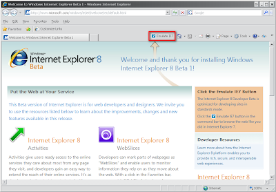
So, the IE8 beta is released today (from here). I downloaded it (begrudgingly let it over-write my IE7 install) and rebooted. The interface is like the spawn of IE6 and IE7. Surprisingly (and I don't expect this to survive the beta) they have added a "Emulate IE7" button. My only grief with it is that you need to restart IE completely before it will take effect.


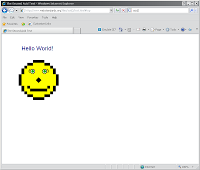
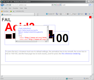
From what I can tell, it -does- pass the Acid2 test (although it remains to be seen if it codes specifically for the acid test, that is beyond my ability to know):
As for Acid 3?


Fail. Now, to be fair, Firefox 3 doesn't render it completely either, but it does get up to 60/100 on my install, and you can actually tell it is a bar gradient, etc.

HOWTO: Run IE6 and IE7 together

If you have ever had the need to test a website in both crappy versions of IE, and you've got IE7 installed, this will help you. Just head over to evolt - Download the IE6 binary, extract it to a folder and run it. Simple.

HOWTO: Dual Monitors in Linux with ATI

After searching for many hours and finding many different howtos that didn't work for me, I thought I'd post what I found actually worked in my case. Note, with the ATI cards in particular in linux, it seems like even the same cards using the same driver versions work differently, so this may not work for you. But unlike a lot of the howtos I've seen, this isn't destructive. This will also assume you have installed the latest version of the ATI proprietary drivers.

My problem in particular was that I'm using two monitors of different sizes and resolutions. It seems like it is easy enough to have two of the same size/resolution monitors. Anyway, I'm running a 20.1" screen as my main with a 1680x1050 resolution, and my secondary is a 17" with 1280x1024 resolution, I also have them set so the secondary monitor is to the left of the main monitor.

ALWAYS BACKUP YOUR xorg.conf FILE BEFORE EDITTING IT!!!! I CAN NOT STRESS THAT ENOUGH - It is possible these changes will cause X to not start and you will need to restore the backup.
cd /etc/X11/
cp xorg.conf xorg.conf.backup

Anyway, If you haven't yet configured the main monitor properly, you need to run
aticonfig --initial
That will change your xorg.config file to add the various ATI stuff. There is a way to use the aticonfig command to setup the dual monitors, but I never was able to get Big Desktop to work properly with it. I'd have two monitors, but they'd be separate (IE, I couldn't move windows from one to the other).

Once aticonfig has set up your xorg.conf file, you need to open it up in your favorite text editor and add these lines to the device section that ATI set up. If your xorg.conf file is as sloppy as mine, you may have several "device" sections, so you are looking for this one:
Section "Device"
Identifier "aticonfig-Device[0]"
Driver "fglrx"
Option "VideoOverlay" "on"
Option "OpenGLOverlay" "off"
EndSection

The important part to look for is the "aticonfig-Device[0]" - this tells you that this is the ATI device.

Next step is to add these lines to your file:
Option "DesktopSetup"  "horizontal,reverse"
Option "Mode2" "1280x1024"
Option "DesktopSetup" "LVDS,AUTO"
Option "EnablePrivateBackZ" "yes"
Option "HSync2" "65"
Option "VRefresh2" "60"

As for what these options mean:
  • Option "DesktopSetup" -> This is how your monitors are physically configured, Horizontal means they are next to each other, and reverse means Monitor 2 is to the left of Monitor 1. Other options are vertical, and not having the reverse modifier there.
  • Option "Mode2" -> This is the resolution of your second monitor
  • Option "DesktopSetup" -> The types of monitors that is connected LVDS = LCD, CRT, AUTO.. leaving this as auto should work.
  • Option "EnablePrivateBackZ" -> This enables 3d support for both monitors.. this may not work but it seems to work for me.
  • Option "HSync2" -> Set the horizontal sync of your second monitor, 65 seems to be a default value for 99% of LCDs
  • Option "VRefresh2" -> Vertical refresh of your second monitor, 60 is mine, you will probably have to look yours up if it doesn't work.
In the end, this is what my device section looks like:
Section "Device"
Identifier "aticonfig-Device[0]"
Driver "fglrx"
Option "VideoOverlay" "on"
Option "OpenGLOverlay" "off"
Option "DesktopSetup" "horizontal,reverse"
Option "Mode2" "1280x1024"
Option "DesktopSetup" "LVDS,AUTO"
Option "EnablePrivateBackZ" "yes"
Option "HSync2" "65"
Option "VRefresh2" "60"
EndSection
As I said, these options work for me. Due to the crappy state of the ATI drivers you may need to play with it. There are a few drawbacks that I've found in that my total resolution should be 2960x1050 however it seems to be 3100x1050, or something similar. I don't notice this since the extra pixels are "off" the monitor. And with the second monitor, there are 26 pixels that fall off the bottom of the monitor, but in practice I've never really had an issue with it.

Please drop a comment if you found this helpful (or if it didn't work for you, what you did to fix it, etc).

Tuesday, March 4, 2008

HOWTO: Prevent a BSoD from disappearing

I'm going to go over the simple steps of setting a Windows XP install to not auto-reboot on a Blue Screen of Death. While this may be nice if you get it once in a while, if, like me, you break something that prevents Windows from booting because of a BSoD having it reboot instantly makes it impossible to see what is going on. Many of you may know this, but I hadn't yet figured out how to do it until last night when I managed to prevent Windows from booting.

Step 1:
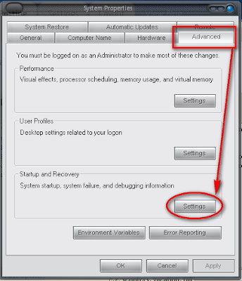
Right click My Computer and go to System Properties (Or, if you like the keyboard, Win+Pause/Break). Click the 'Advanced' tab.


Step 2:
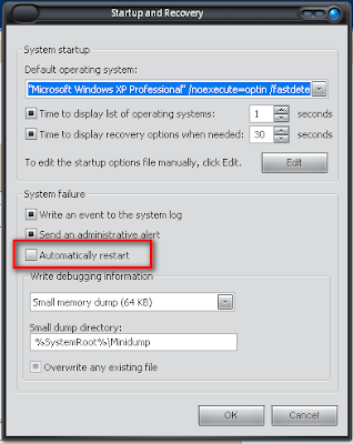
Click 'Settings' under 'Startup and Recovery'. Under the System Failure heading, uncheck 'Automatically Restart'.


Now, when you BSoD, you'll actually be able to -read- the error message and try to solve the problem. In my case it was a corrupt vidstub.sys file.

UPDATE:
If you are unable to even boot in to safemode to get this done, there is help!
First, you need to download a boot disk that has a registry editor. I recommend:
http://www.ultimatebootcd.com/
It's been a while since I've used it, but it has always worked for me.
Open up the registry editor (It's under NTFS tools) and edit this key (Odd formatting because of limit in width of the blog):
HKEY_LOCAL_MACHINE\
SYSTEM\
ControlSet001\
Control\
CrashControl

Change AutoReboot key to 0

Hope that helps!

Saturday, March 1, 2008

HOWTO: Linux/Rst-B Scanning

As much as we all love to rave about how secure *nix installs are, it -is- still possible to get infected by the one or two variants of malware out there. Some admins (myself included at points) get lulled into a sense of security knowing that we've got billions of Windows machines acting as human shields to protect us, but we do need to take steps to make sure we don't become part of the botnet brigade.

There is one package out there (Linux/Rst-B) that seems to be the most common (relatively speaking) issue out there for *nix, and there is a handy tool for detecting it. It comes with a pre-compiled binary for Debian (which works in Ubuntu as well).

We're going to put it in /usr/local/sbin, so that it is on the path for later on:
sudo su -
cd /usr/local/sbin/
wget http://www.sophos.com/support/cleaners/detection_tool.tar.gz
tar xvfz detection_tool.tar.gz
I realize that you can just sudo the wget and extraction commands if you don't have write privs on sbin/, but hey, I'm lazy.

This will extract the detection_tool/ directory, which gives you the source and the pre-compiled binaries. To compile from source:
cd /usr/local/sbin/detection_tool
make
Copy the binary to the sbin/ directory with link:
ln -s /usr/local/sbin/detection_tool/pre-compiled/detection_tool /usr/local/sbin/rst_detection_tool

OR, if compiled from source:
ln -s /usr/local/sbin/detection_tool/detection_tool /usr/local/sbin/rst_detection_tool

To use:
rst_detection_tool [-v] (path)

So to scan the entire filesystem:
rst_detection_tool /

If all is well, you'll get this output:
root@ubuShock:/usr/local/sbin# rst_detection_tool /
Sophos Rst-B Detection Tool
---------------------------
Copyright (c) 2008 Sophos Plc. All rights reserved.

Scanned 681699 files, found 0 infections of Linux/Rst-B.
End of scan.
root@ubuShock:/usr/local/sbin#

Anyway, best of luck.

NOTE: This howto taken from Howtoforge - Which is a great place for howtos relating to linux. I've altered it a bit to make it a bit easier to read IMHO.

Thursday, February 14, 2008

HOWTO: Mac OSX on a Windows Machine


For this you will need a mac (or a hackintosh) running OSX. This is basically a way to connect multiple users simultaneously to the mac system, a la XDMCP for Linux. The performance isn't quite as good as XDMCP since it uses the VNC protocol, but it is very much usable over a LAN.

All these steps are to be done on the Mac..
Step 1: Create a secondary account. This will be the account you log in to.

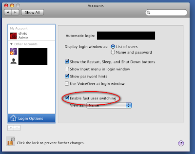
Step 2: In the account section in the System Prefrences, open up the Account section, and browse to 'Login Options'. Open this up and enable 'Fast User Switching'


Step 3: Switch to the account you want to be able to connect to via fast user switching. This is accomplished by clicking the user name in the upper right corner and selecting the name you created in step 1.

Note (Thanks John): You need to disable the built-in Leopard screensharing via the Sharing option in System Preferences before installing and using Vine if you have it enabled (It is off by default)

Step 4: Download and install Vine (This is a standalone vnc server. Use this instead of the inbuilt VNC server.) from HERE - You will want to get the 3.0 package.

Step 5: Run the vine server, and set it to open at login by right clicking the icon on the dock, and enabling 'Open at Login'

Step 6: Switch back to your original account

Step 7: Download a vnc client for windows, and connect to the IP address of your mac. If everything went according to plan, you should have your mac desktop sitting on your windows desktop.

A few notes:
You should be able to adjust the screen resolution of the other user without a problem, although there are reports that it can do some odd things to the resolution of the primary user. Basically what happens is this - If you switch on the mac to the secondary user, the display resolution gets overwritten to the default, and you need to change it back with vnc.

Also, if you reboot, you will have to re-login to the secondary account in order to be able to connect.

And hey, if you found this helpful, please leave a comment and click my google ad.

Update: A commenter (John) has recommended that on the windows client, you set the encoder to zlibHex and the compression to 1 for best performance.

Search.

Google